One-sentence overview: From the shipping list, to wiring & installation, then set PWM in BIOS—all in one go.
Add active cooling to your ZimaBoard 2 mini NAS / home server / self-hosted node for sustained NVMe, 10GbE, and local AI workloads.
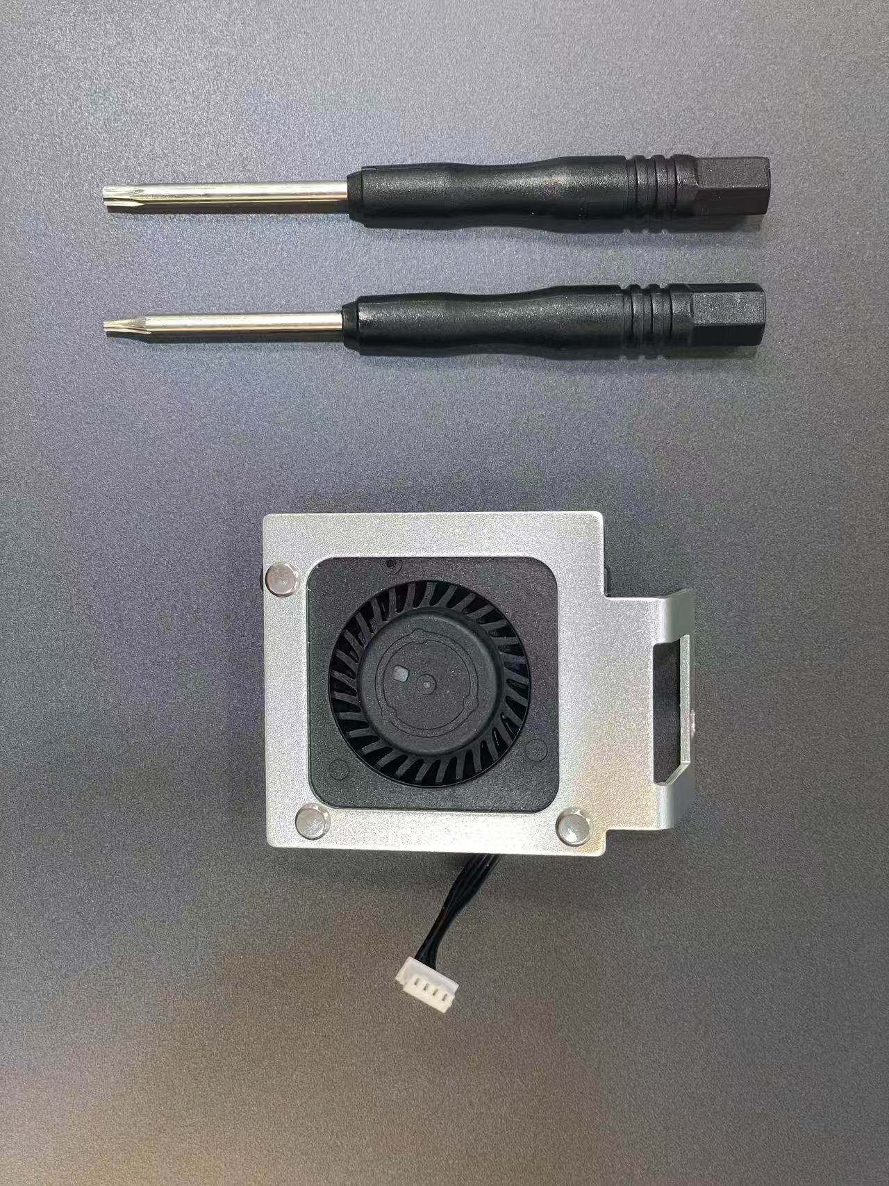
Shipping List
- 1x PWM fan module (with 4-pin PWM cable)
- 1x T5 Torx screwdriver (rear cover)
- 1x T10 Torx screwdriver (fan mounting)
Fan Installation
- Shut down the device and unplug the 12V power adapter.
- Wait until the Power LED is off and the heatsink is cool.
- Work on a clean, ESD-safe surface.
Steps
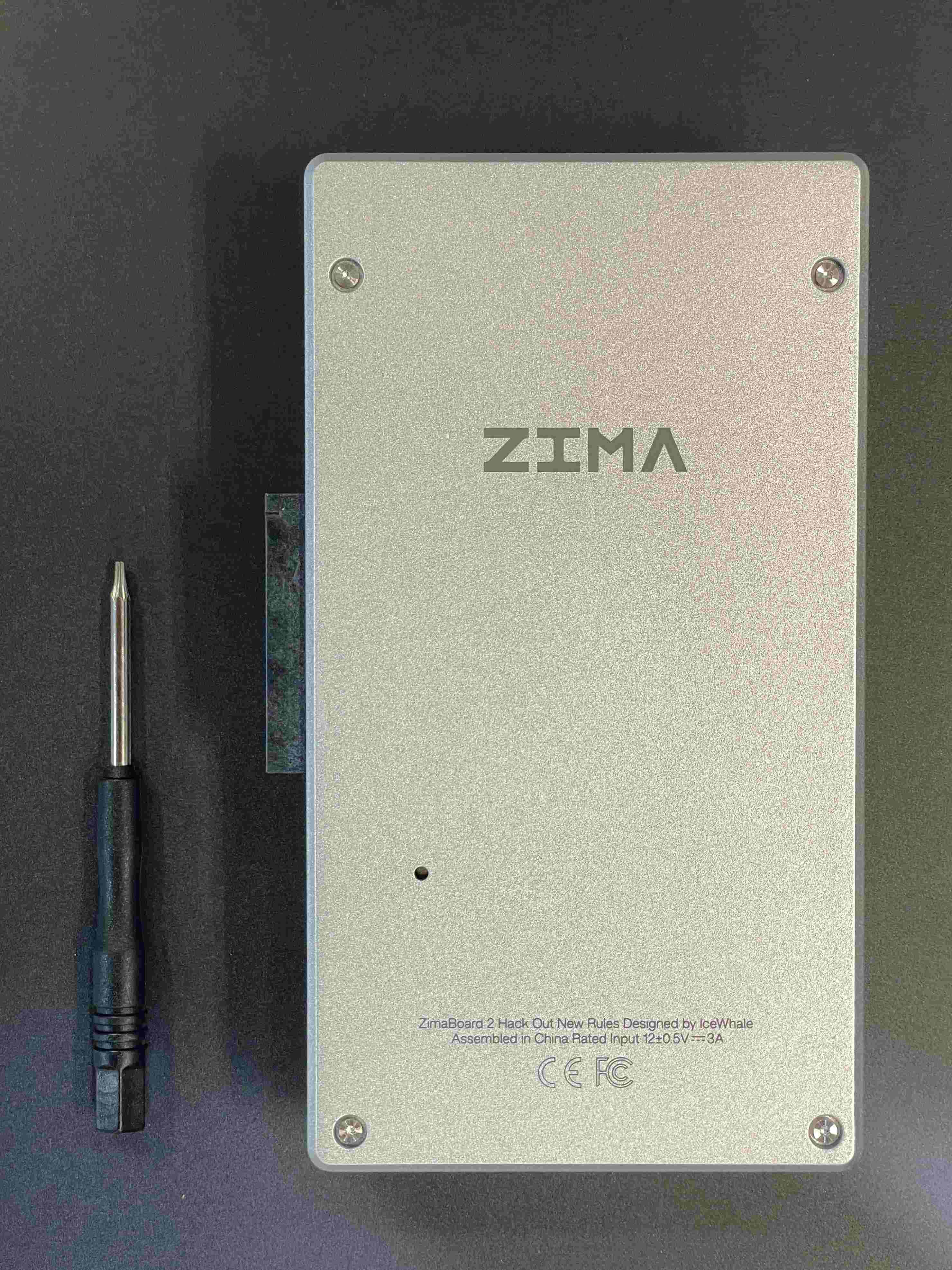
- Remove rear cover (T5): Unscrew the T5 screws and lift the cover straight up.
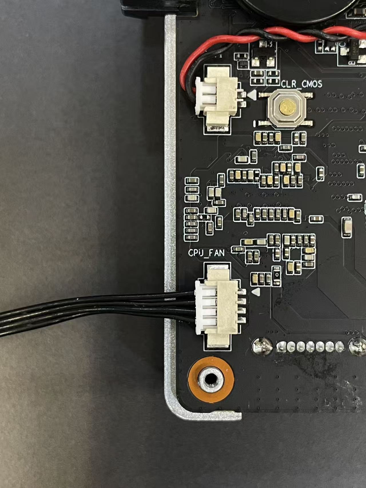
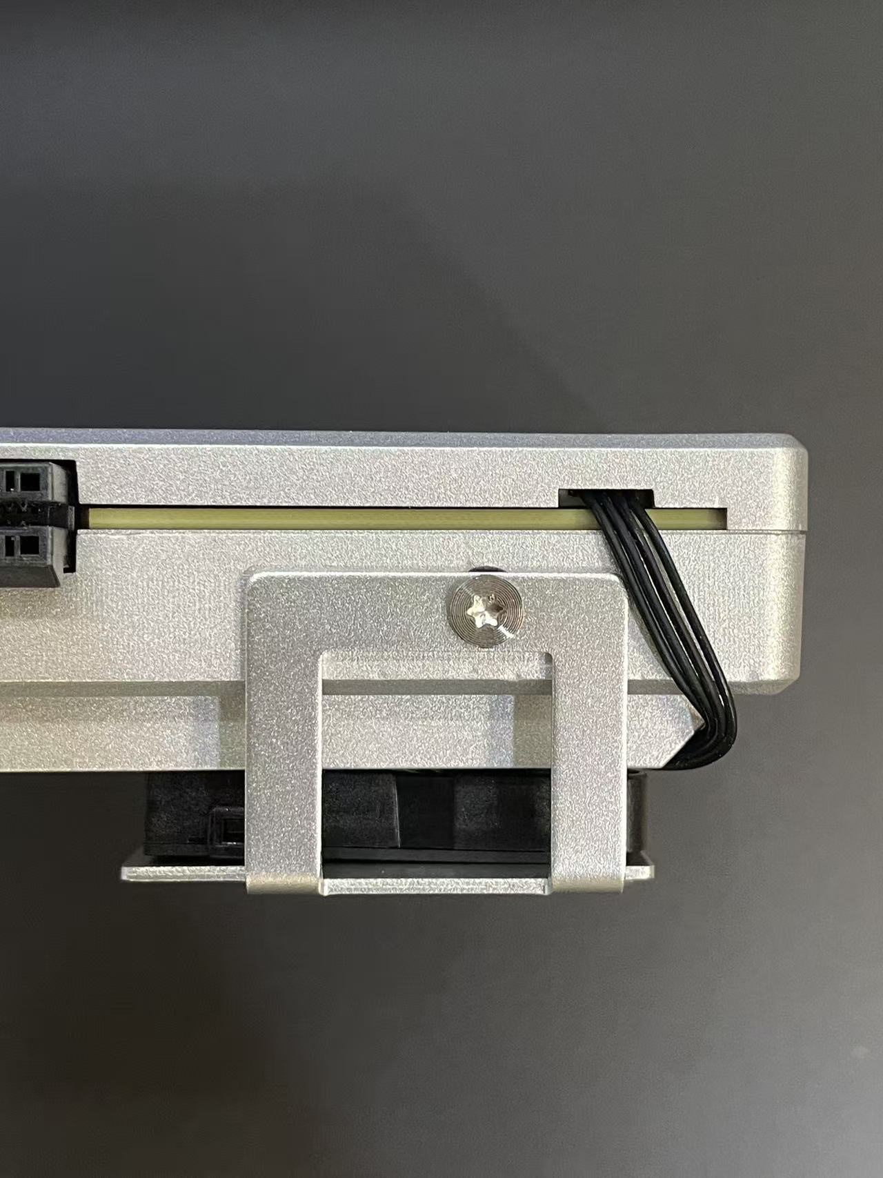
Plug 4-pin PWM fan cable: Locate the CPU_FAN header; align the keyed connector and insert.
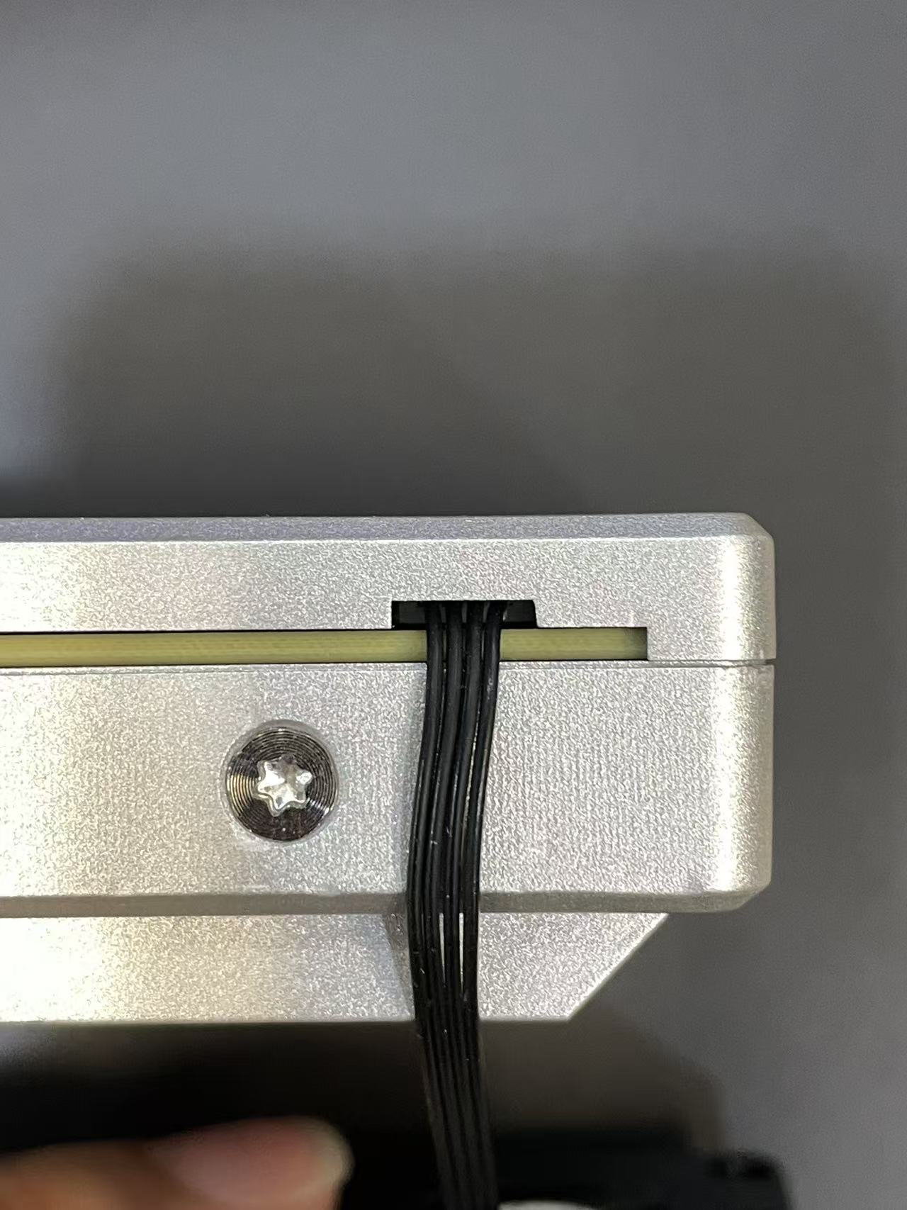
Route cable & refit cover: Lead the cable through the side notch; reinstall the rear cover and tighten the T5 screws evenly.
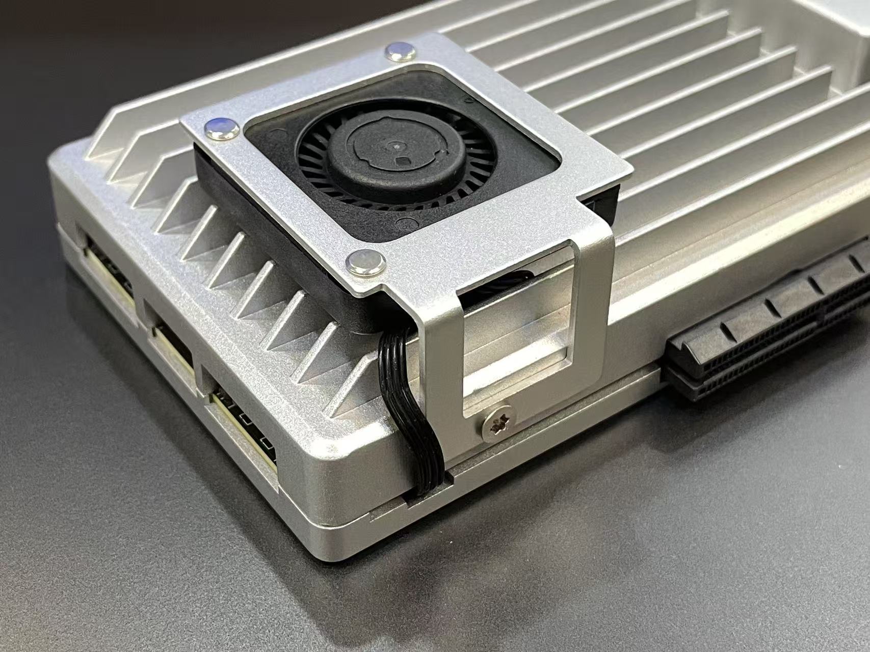
Mount the fan (T10): With the airflow into the fins (per diagram), fasten the fan to the heatsink using the T10 screws; secure firmly without over-torque.
Congratulations! — Installation complete.
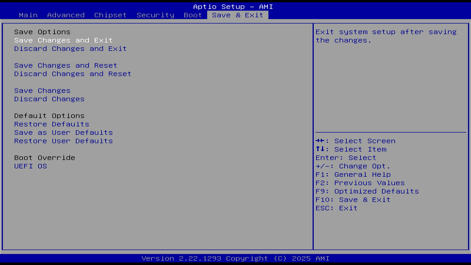
Set PWM in BIOS (if needed)
Power on and press Delete to enter BIOS Setup.
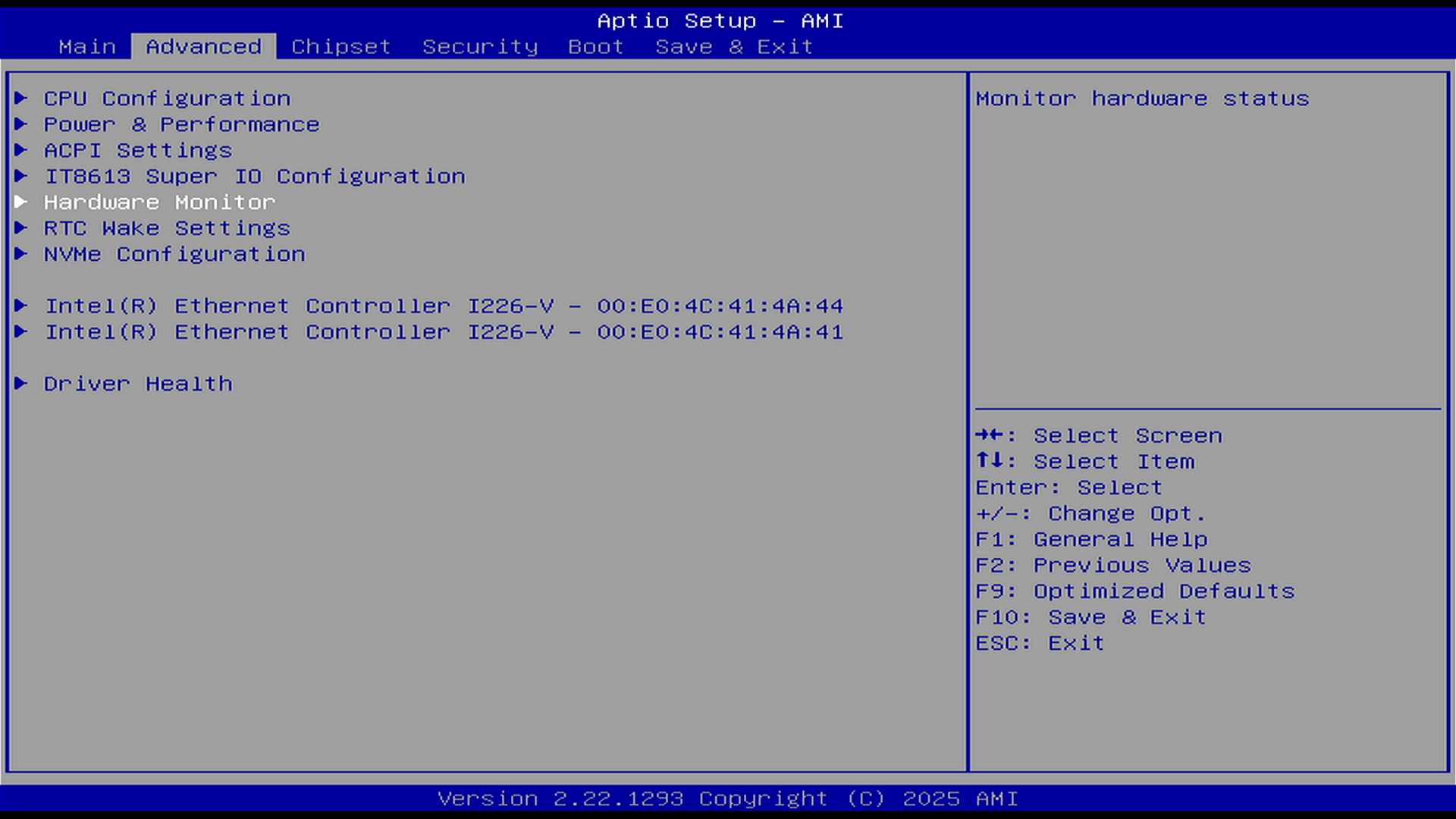
Open Hardware Monitor.
Choose your preferred fan control mode (e.g., PWM with a curve, or a fixed duty).
Save & Exit (F10), then confirm the fan spins after reboot.
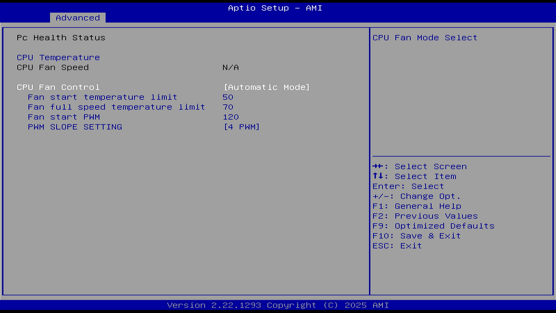
BIOS Fan Control Options (Explanation)
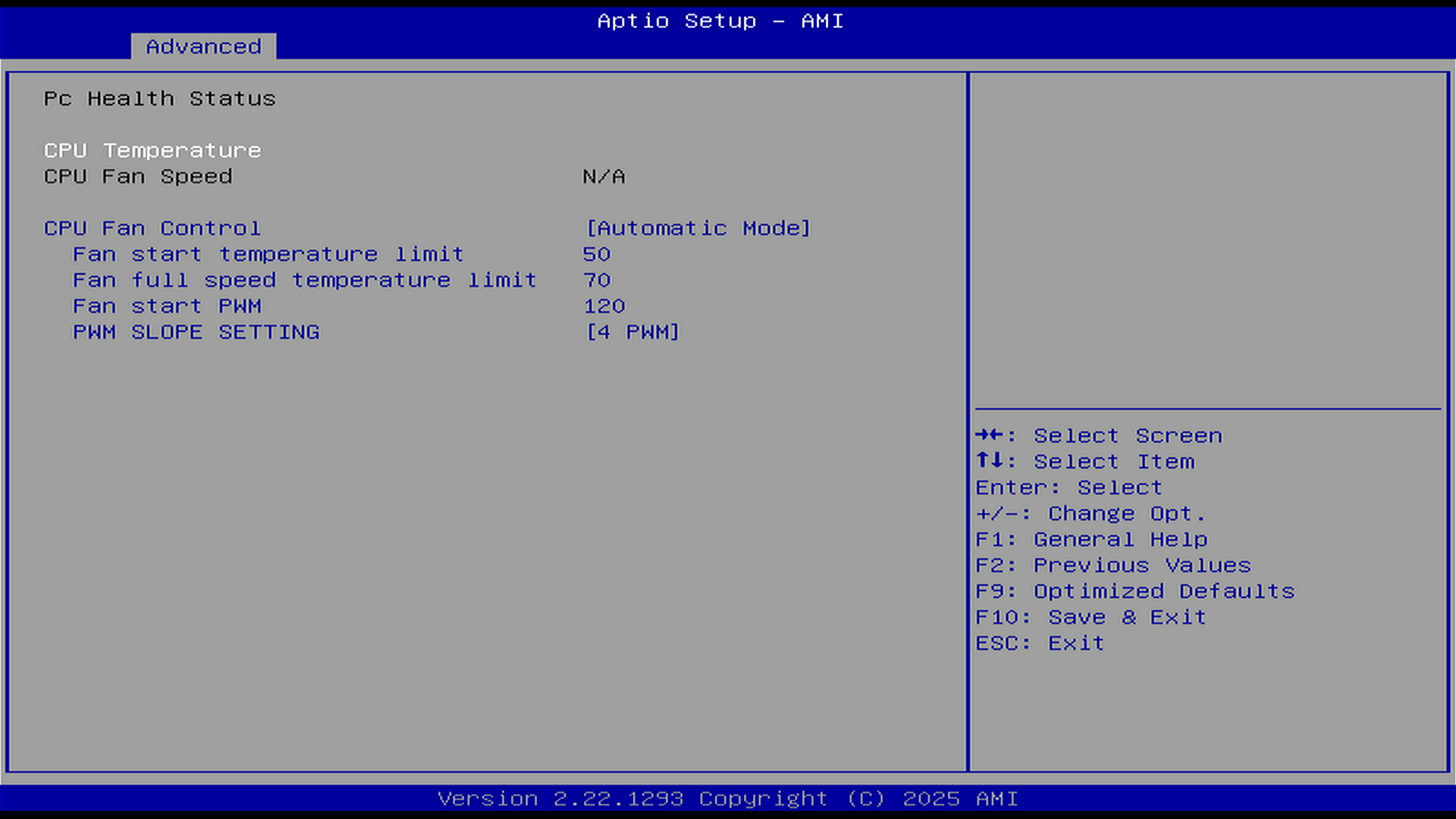
- PWM Auto Mode
- Fan Start Temperature: Fan control engages automatically once CPU temp ≥ start point (range: 0–100 °C).
- Fan Full-Speed Temperature: When CPU temp ≥ this point, the fan jumps to 100% (range: 0–100 °C; must be greater than Start Temperature).
- Fan Start PWM: Initial (minimum) fan speed after ZimaBoard 2 powers on (range: 0–255; 255 = 100%).
Example: To set “Fan off when temperature is below Fan Start Temperature”, set to 0. - PWM SLOPE SEETING: Duty increment for each +1 °C rise (range: 0-15).
- Fixed Duty Mode
- Fixed Fan Duty: Run the fan at a constant speed (range: 0–255; 255 = 100%).
**Note**: The PWM value (0–255) represents the duty cycle / effective drive level rather than a direct RPM percentage. Fan speed is not linear with PWM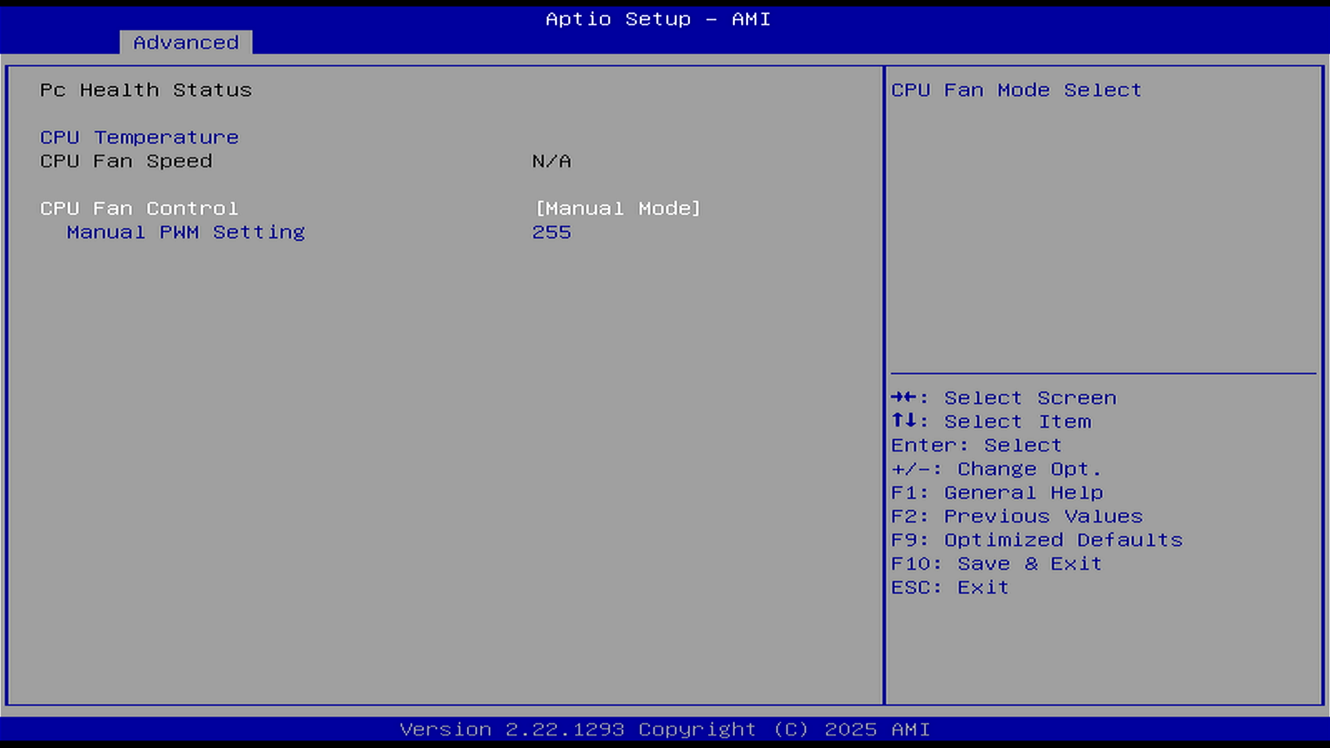
Troubleshooting
- Fan won’t spin:
- Reseat the 4-pin connector; ensure the header/mode is enabled.
- Verify the fan’s minimum PWM start threshold (don’t set duty too low, each fan has a different minimum starting PWM).
- Noise / vibration: Re-align the fan and tighten the screws.
- Won’t power on after install: Remove the fan PWM lead and try again. If the CMOS reset button was pressed accidentally, the first boot may take ~2 minutes for POST/self-test.
- Fan doesn’t stop at PWM 0:This is by design to prevent stalling and ensure minimum cooling. Many fans have a hardware-enforced minimum PWM speed.