This guide applies to the ZimaCube series and walks through removing and replacing the hard-drive backplane. Follow the steps in order; reassemble by reversing the disassembly steps.
Tools You Will Need
- M3 Phillips screwdriver (for the backplane and bracket screws)
- H2 Hex screwdriver (for the side panel screws)
- Tweezers or a plastic spudger (recommended, for prying off the clip-on panel and peeling back the black tape)
Important Notes
Power off and dischargeBefore replacing the backplane, power off the device and unplug the power cord. Wait about 30 seconds for residual power to drain, to avoid electric shock or component damage.
ESD protectionTouch a metal surface or wear an anti-static wrist strap before handling components, to avoid damaging the backplane.
- Screws from different locations may differ in length. Keep them sorted so each goes back in the right place.
- The flat cables (FPC) are fragile. Peel the tape, lift the latches, and plug or unplug them gently to avoid tearing the cable or breaking a latch.
- When plugging or unplugging connectors, grip the connector itself. Never pull on the wires.
- The flat cables are keyed and fit only one way. Take a photo to record the orientation before removing them, align with the keyed notch when reinstalling, and never force a connector that will not seat.
Disassembly Steps
1. Power off and remove the drives
- Power off the device and unplug the power cord.
- Remove all drive trays (including the seventh-bay tray) and set them aside safely.
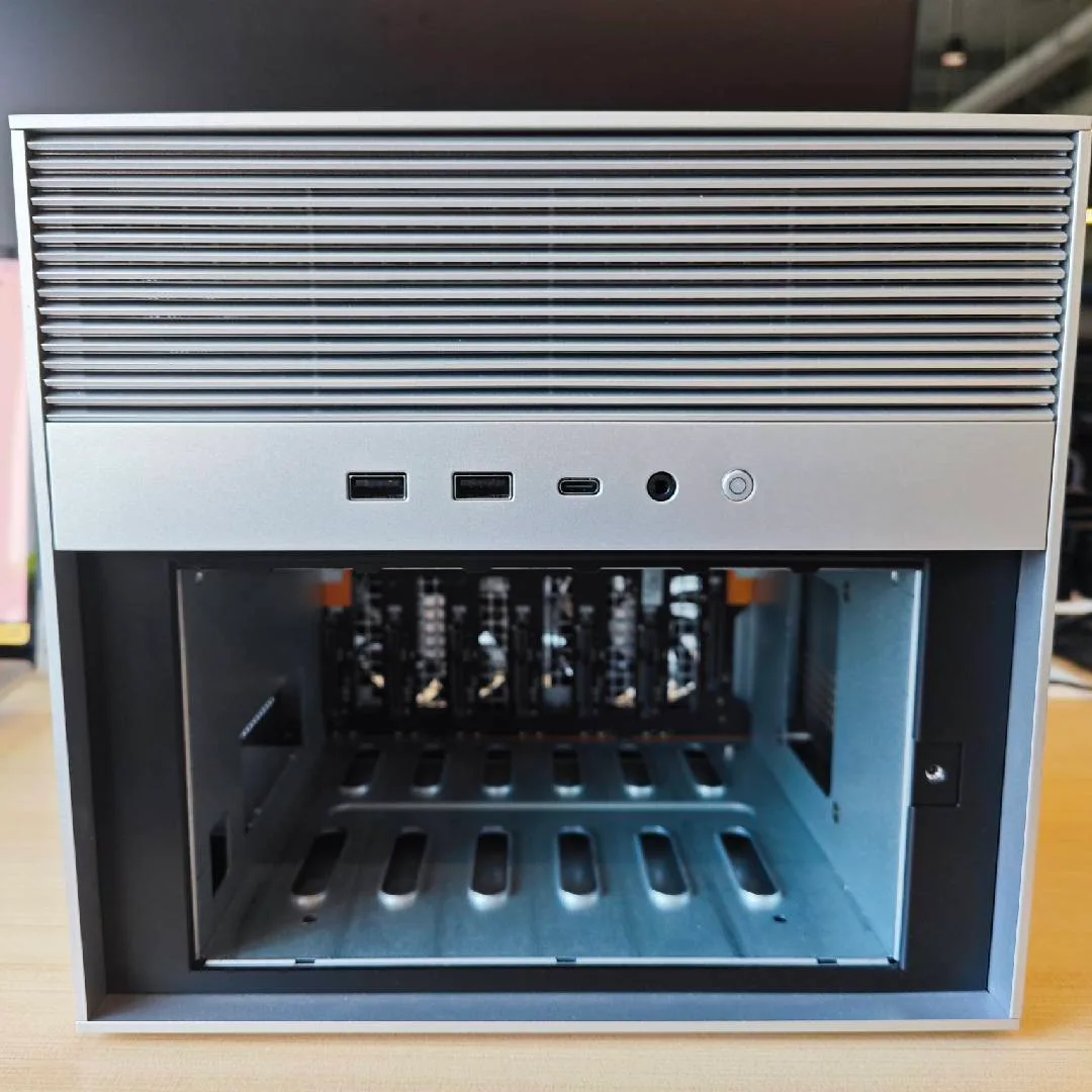
2. Remove the side panels and open the top cover
- Remove the fixing screws on both sides of the chassis (4 per side).
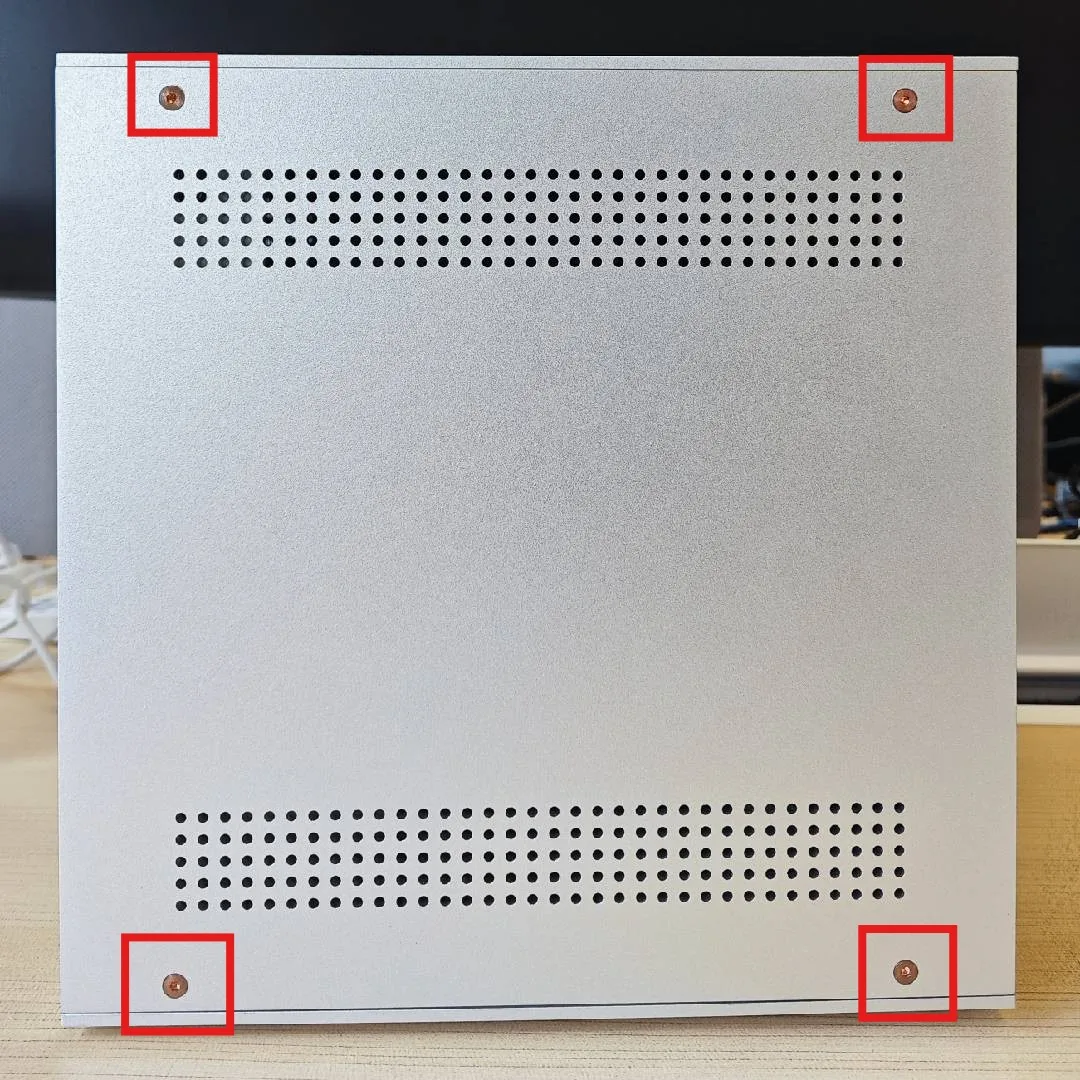
- Open the top cover.
- Lift the side panels upward to make room for later cable access.
3. Remove the rear panel and bracket
- The rear panel is clip-mounted. Simply pry it open and remove it.
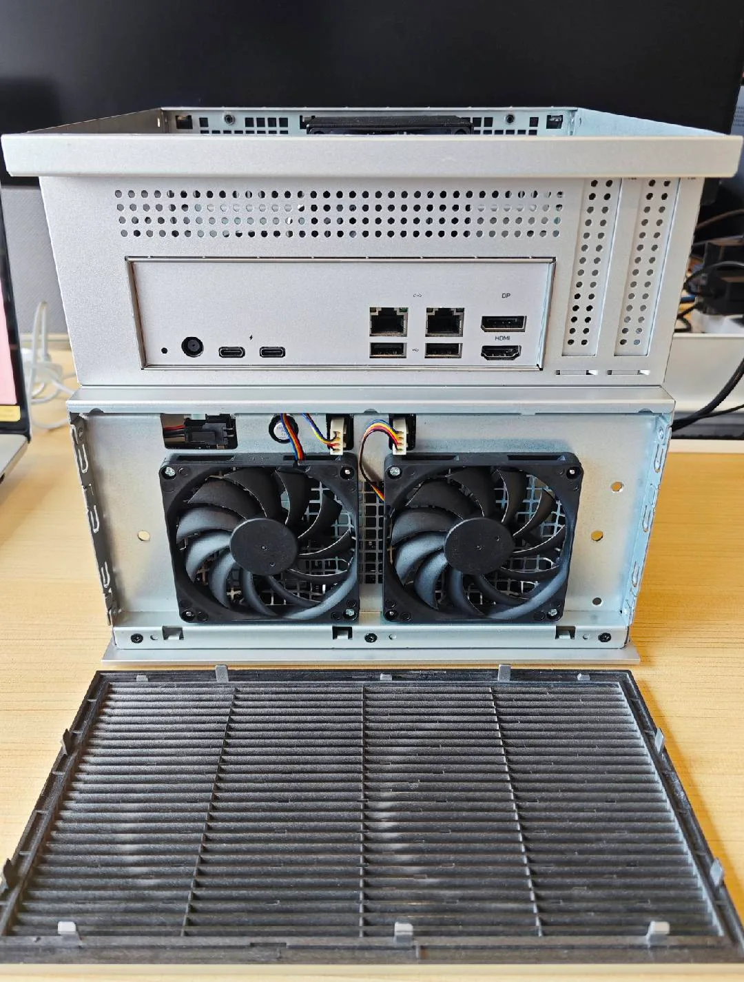
- Remove the 6 screws on the rear bracket (located behind the clip-on panel, securing the fans and backplane), and unplug the two fan connectors.
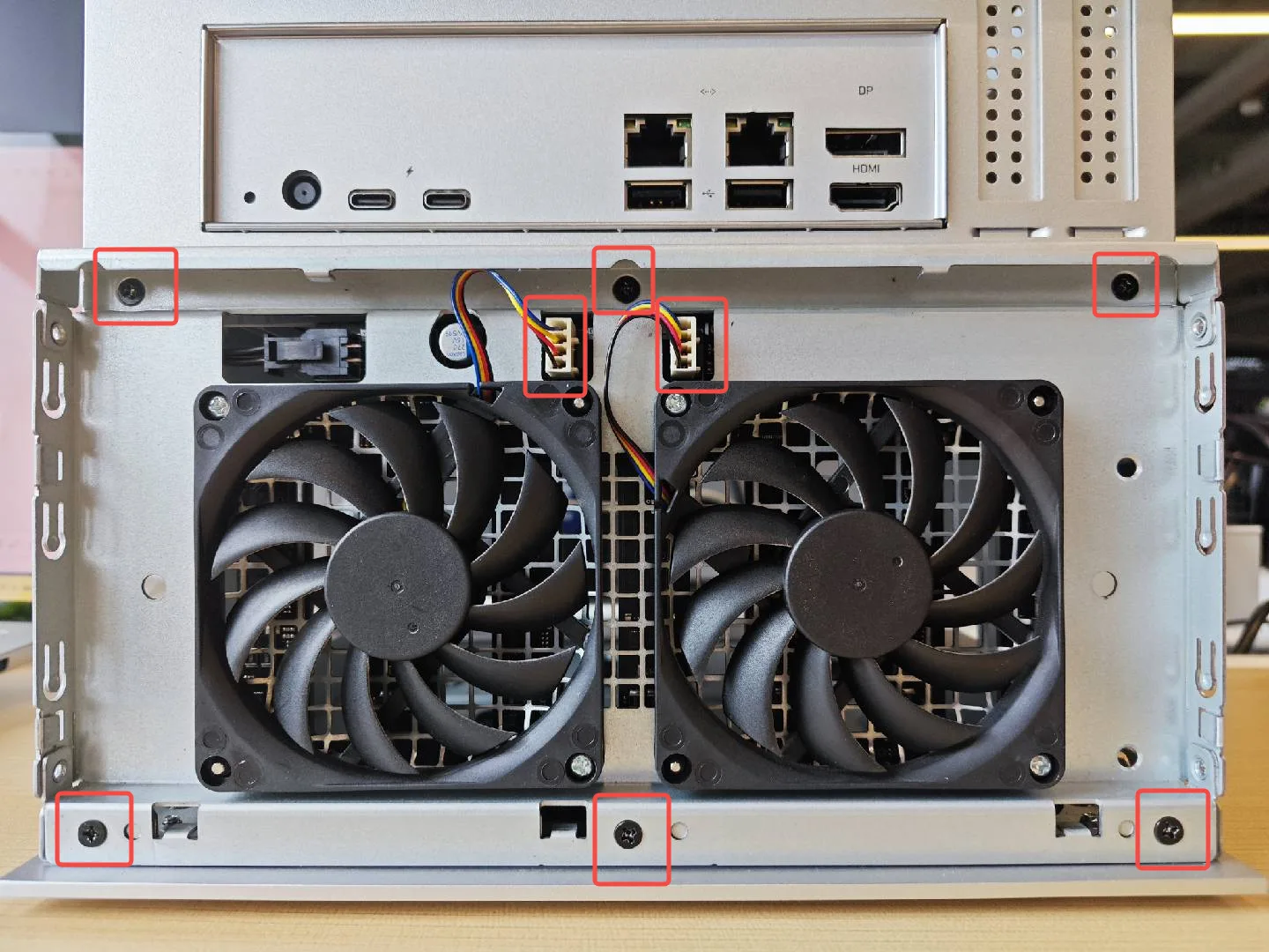
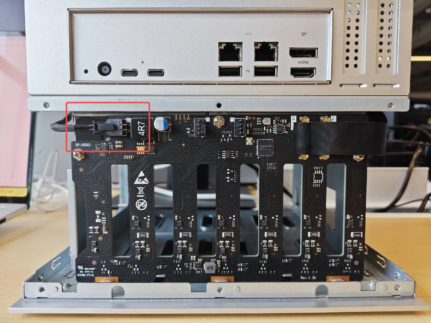
4. Disconnect the backplane power cable
- Unplug the backplane power cable on the left side.
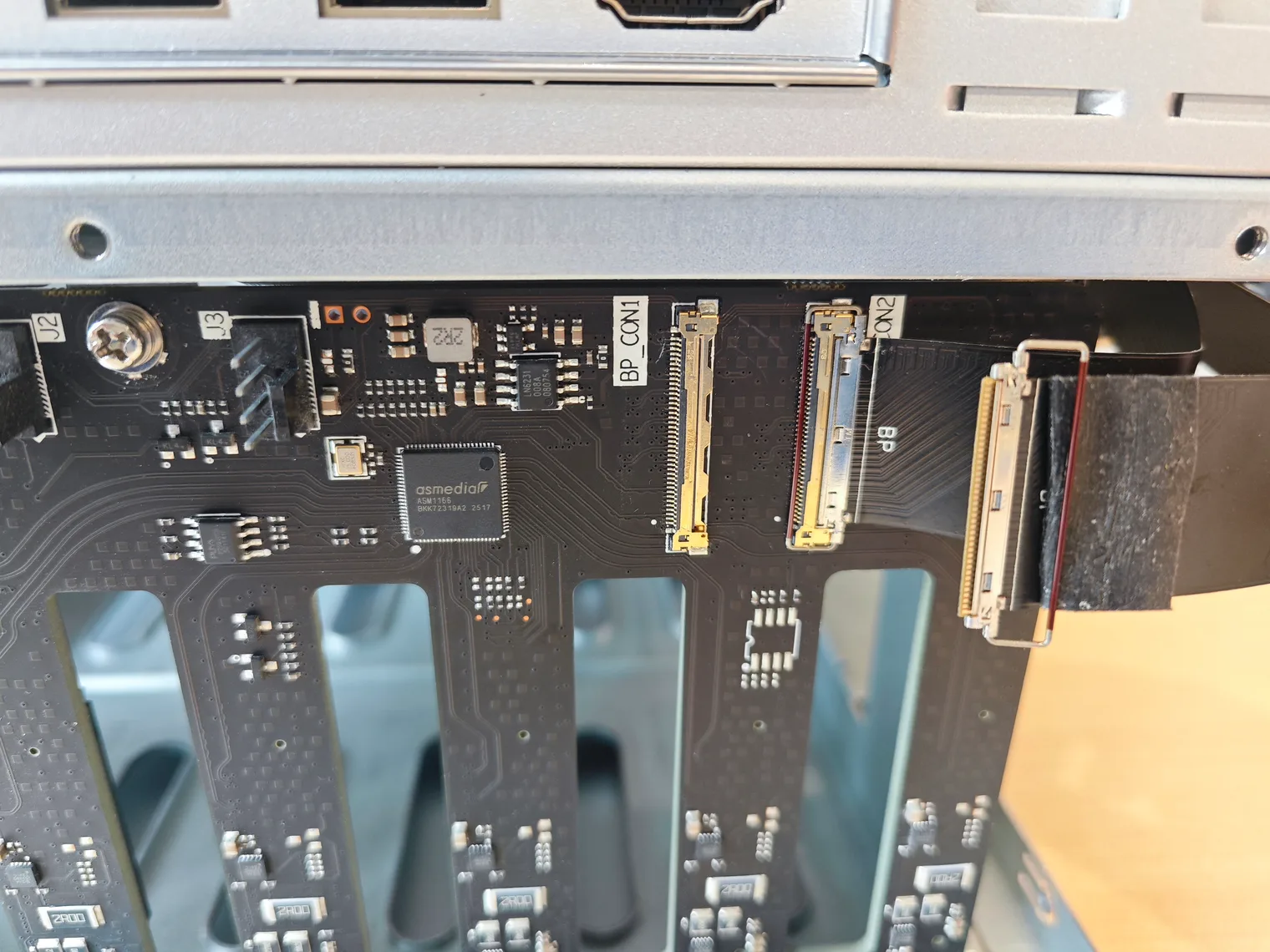
5. Remove the flat cables
- Carefully peel off the black tape on the flat cables.
- Lift the latches on both flat-cable connectors one at a time, then gently pull the cables out.
- Both ends of each cable are handled the same way. Keep the orientation consistent (the connector is keyed), and align with the keyed notch when reinstalling.
6. Remove the old backplane
- Remove the 3 screws on the backplane.
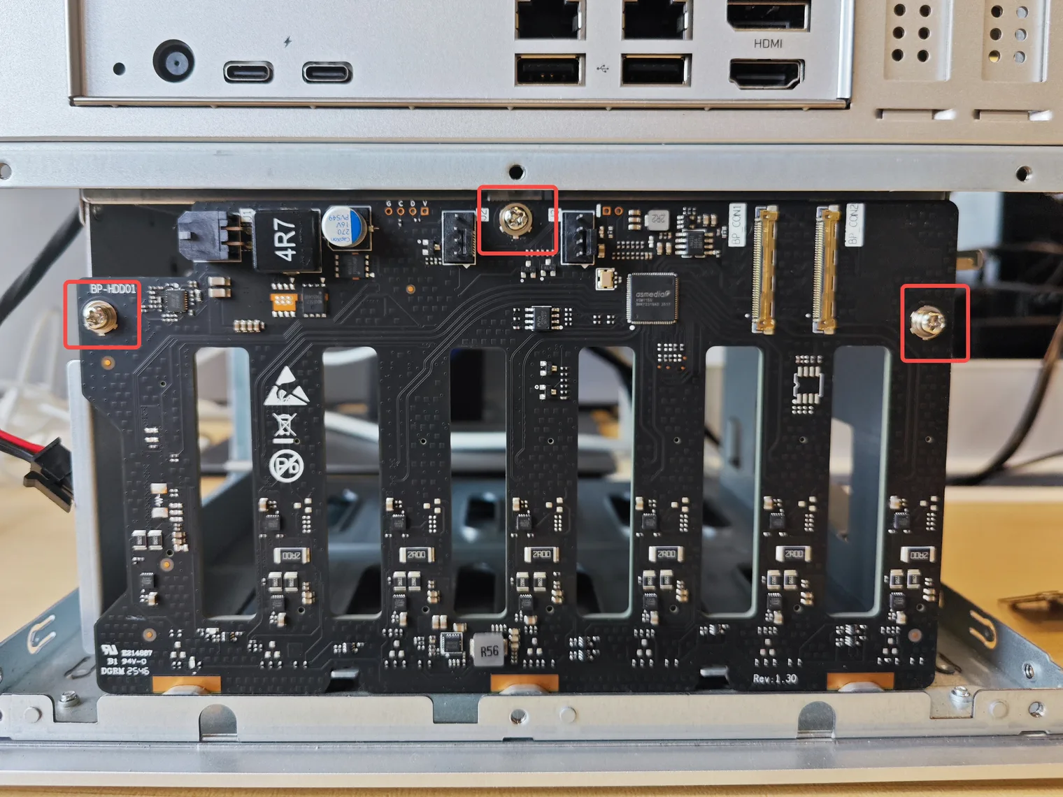
- Gently lift out the old backplane.
Install the New Backplane
1. Install the new backplane and reconnect the cables
- Place the new backplane into position and align the screw holes.
- Secure it with the 3 backplane screws.
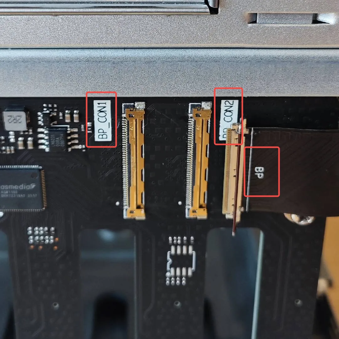
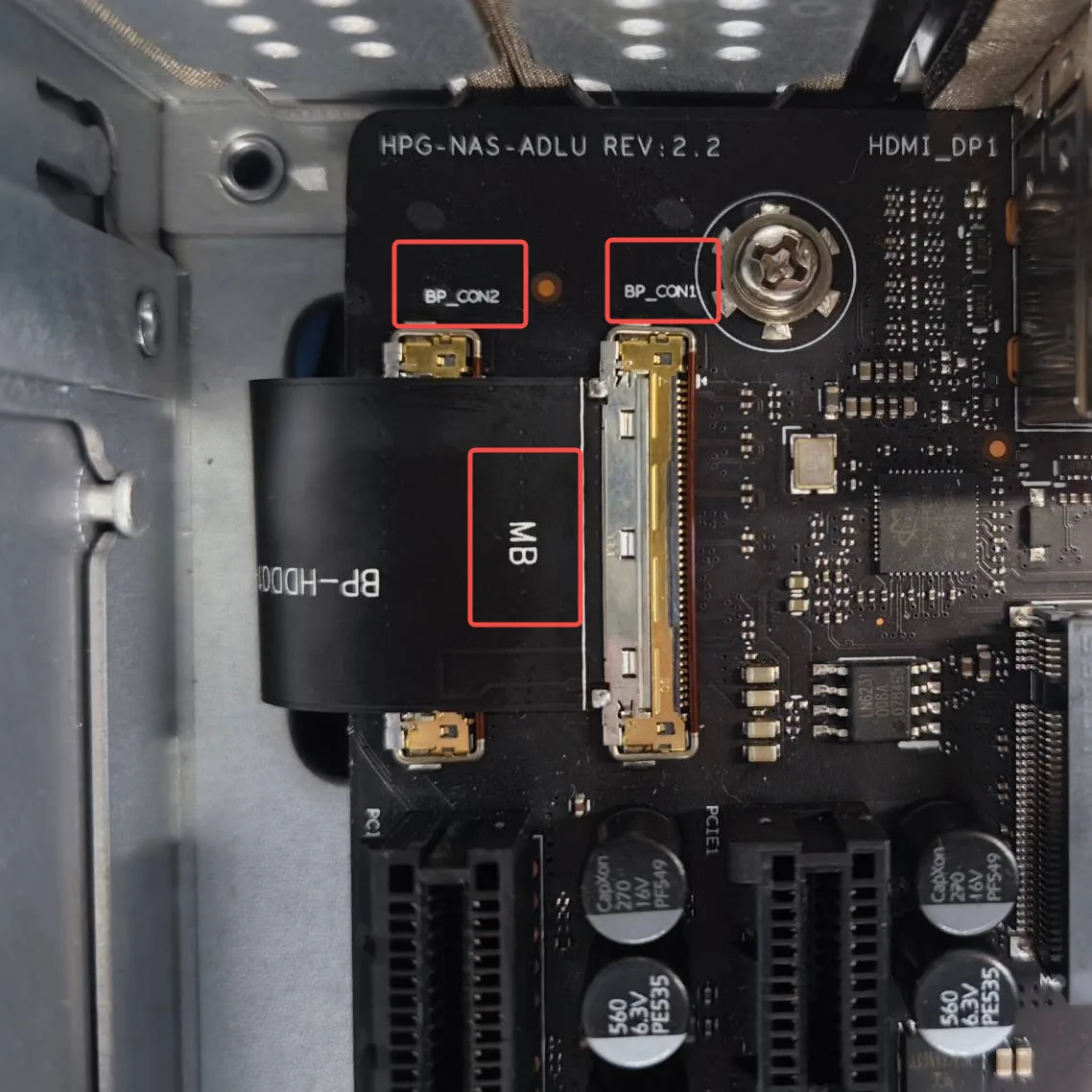
- Reconnect the flat cables: plug the CON1 and CON2 cables into their corresponding slots, matching the labels on the backplane and motherboard. Align with the keyed notch, insert, press the latch down, and re-apply the black tape.
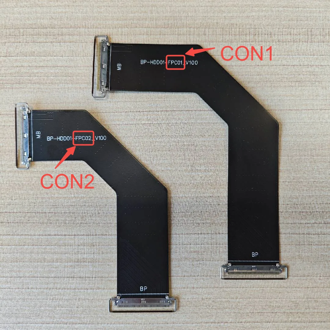
How to tell the two cables apart (see the figures below): CON1 is the longer cable and CON2 the shorter, each labeled on the cable. The end marked “BP” plugs into the backplane, and the end marked “MB” plugs into the motherboard.
Flat cables are universalThe flat cables are universal and work with both first-generation and second-generation Cubes.
2. Reassemble in reverse order
- Plug the backplane power cable back in on the left side.
- Reinstall the rear bracket, reconnect the two fan cables, and tighten the 6 screws.
- Snap the rear clip-on panel back into place.
- Reinstall the two side panels.
- Replace the top cover.
- Tighten the screws on both sides of the chassis (4 per side).
- Reinstall all drive trays (including the seventh-bay tray).
3. Power on and verify
Connect the power, power on, and confirm the fans spin normally and all drive bays are detected correctly.
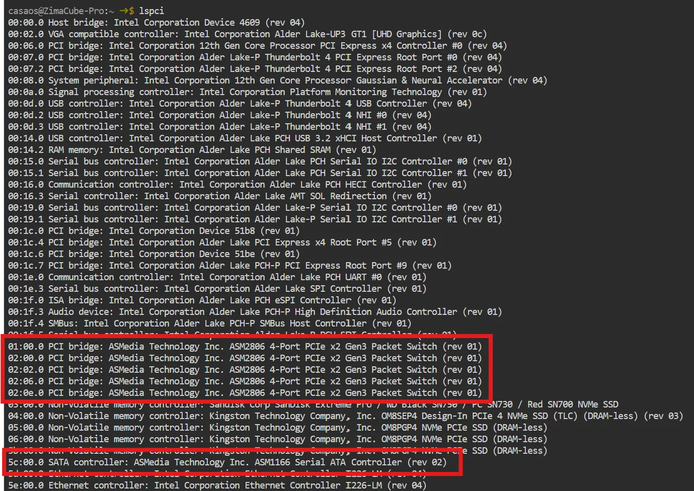
Run lspci in the terminal: if you see the two parts circled in the image below, the replacement is successful.